


Size of this PNG preview of this SVG file: 800 × 533 pixels. Other resolutions: 320 × 213 pixels | 640 × 427 pixels | 1,024 × 683 pixels | 1,280 × 853 pixels | 2,560 × 1,707 pixels | 1,500 × 1,000 pixels.
Original file (SVG file, nominally 1,500 × 1,000 pixels, file size: 31 KB)
| Description |
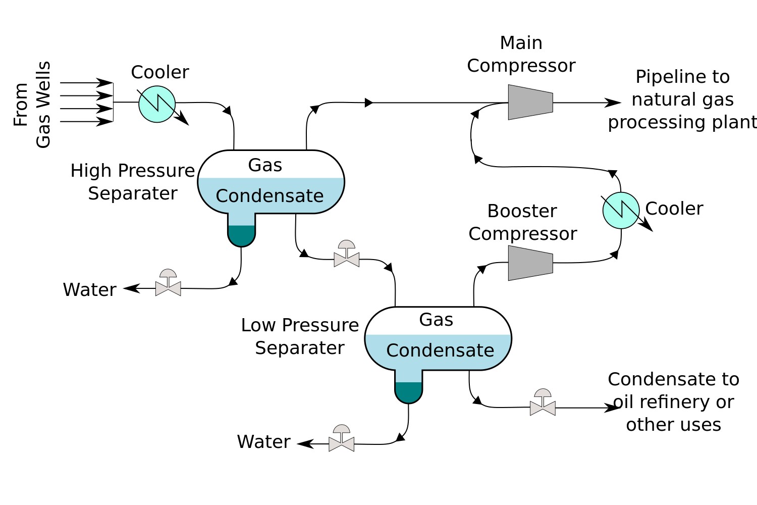
This is a schematic flow diagram of a typical facility for separating and recovering liquid condensate from raw natural gas. Based on the drawing by Mbeychok. |
| Date | (UTC) |
| Source | |
| Author |
|
| This is a retouched picture, which means that it has been digitally altered from its original version. Modifications: Vectorized. The original can be viewed here: NaturalGasCondensate.png:
|
I, the copyright holder of this work, hereby publish it under the following license:

|
Permission is granted to copy, distribute and/or modify this document under the terms of the GNU Free Documentation License, Version 1.2 or any later version published by the Free Software Foundation; with no Invariant Sections, no Front-Cover Texts, and no Back-Cover Texts. A copy of the license is included in the section entitled GNU Free Documentation License. |
| This file is licensed under the Creative Commons Attribution-Share Alike 3.0 Unported license. | ||
| ||
| This licensing tag was added to this file as part of the GFDL licensing update. |
Original upload log
This image is a derivative work of the following images:
- File:NaturalGasCondensate.png licensed with GFDL
- 2007-01-18T23:45:16Z Mbeychok 298x204 (6412 Bytes) I drew this flow diagram myself, using Micrpsoft's Paint program, and uploaded it into the English Wikpedia a day or so ago. I am now uploading it into Commons. - ~~~~
Uploaded with derivativeFX
File history
Click on a date/time to view the file as it appeared at that time.
| Date/Time | Thumbnail | Dimensions | User | Comment | |
|---|---|---|---|---|---|
| current | 01:02, 25 May 2009 | | 1,500 × 1,000 (31 KB) | Jak | something wrong |
| 01:00, 25 May 2009 |  | 1,500 × 1,000 (31 KB) | Jak | fixed some issues with the fonts | |
| 00:57, 25 May 2009 |  | 1,500 × 1,000 (31 KB) | Jak | {{Information |Description=This is a schematic flow diagram of a typical facility for separating and recovering liquid condensate from raw natural gas. Based on the drawing by Mbeychok. |Source=*File:NaturalGasCondensate.png |Date |
File usage
The following page uses this file:
Global file usage
The following other wikis use this file:
- Usage on da.wikipedia.org
- Usage on sv.wikipedia.org