


The Graphics Lab is a project to improve the graphical content of the Wikimedia projects. Requests for image improvements can be added to the workshop pages: Illustrations, Photographs and Maps. For questions or suggestions one can use the talk pages: Talk:Graphics Lab, Talk:Illustrations, Talk:Photographs and Talk:Maps.
This specific page is the requests page for the illustration workshop. Anyone can make a request for an illustration to be improved or created for a Wikipedia article. Clicking the "New Request" button will bring you to a standard template for submitting requests, as well as general advice that should be followed.
| Advice to requesters |
|---|
|
All requests:
SVG requests:
|
|
Requests from recent years:
| |
| For graphists: |
Flag and arms of Plomelin - corrections


- Article(s)
- All articles these already appear on.
- Request
- Could somebody please modify the above files representing the flag and coat of arms of Plomelin, so that they look closer to the way they actually should? The proper version of the flag can be seen here and here. And the full version of the arms can be seen here (albeit obviously without the captions at the top and bottom). Thanks. Snow Lion Fenian (talk) 14:47, 11 October 2024 (UTC)
 Bumping thread. Snow Lion Fenian (talk) 12:37, 10 November 2024 (UTC) Bumping thread. Snow Lion Fenian (talk) 10:39, 2 January 2025 (UTC) Bumping thread. Snow Lion Fenian (talk) 13:43, 3 February 2025 (UTC)
 - Discussion
-
- Is the dragon meant to be identical between the coat of arms and the flag? Just asking, since that coat of arms image that you sent is by far the highest quality version I've been able to find, so I'd like to use it as a reference for both.
- DeVosMax [ contribs • talk • created media ] 05:29, 3 December 2024 (UTC)
- @DeVos Max: Yes, I agree that the dragon from the version of the COA in the link should be used as a reference in the update of both files. Thanks for your interest! Snow Lion Fenian (talk) 15:52, 3 December 2024 (UTC)
- I think the dragon shown on this drawing looks very close to the ones on the flag. I will vectorize this drawing from scratch and use it for the files.
- I think the dragon shown on this drawing looks very close to the ones on the flag. I will vectorize this drawing from scratch and use it for the files.
- @DeVos Max: Yes, I agree that the dragon from the version of the COA in the link should be used as a reference in the update of both files. Thanks for your interest! Snow Lion Fenian (talk) 15:52, 3 December 2024 (UTC)

Feitidede ☆゚.* 20:10, 3 January 2025 (UTC)
- @Snow Lion Fenian I have overwritten both files. I designed the new dragon from scratch based on the image linked above. Let me know if you find any issues.
 Done Feitidede ☆゚.* 04:31, 4 January 2025 (UTC)
- @Snow Lion Fenian I have overwritten both files. I designed the new dragon from scratch based on the image linked above. Let me know if you find any issues.
 Undone: The overwritten versions of the arms and the flags have been restored, as these overwrites, mainly, are conflicting with Commons:Overwriting existing files ; morevoer, the specific design of an element doesn't make the arms or the flag invalid, thus current versions are fully compliant with their description. Ping @Bzh-99 and Jpgibert:
- --Kontributor 2K (talk) 14:05, 4 January 2025 (UTC)
- The current files have clear mistakes in rendering and are even flagged as improper SVGs. The current files also are not compliant with their description because they are missing the colleté d'hermine. The overwritten versions don't appear to vastly differ from the original ones. I can't believe these versions are being gate-kept from being improved. Feitidede ☆゚.* 18:16, 4 January 2025 (UTC)
- @Feitidede: Thank you for your undertaking of this request. Given the apparent dispute over the matter of overwriting the existing files, I would instead propose uploading the correct versions of the flag and arms as completely new files, for which I've provided potential titles above (both of which use the native Breton name of the town to avoid confusion with the existing files).
- The current files have clear mistakes in rendering and are even flagged as improper SVGs. The current files also are not compliant with their description because they are missing the colleté d'hermine. The overwritten versions don't appear to vastly differ from the original ones. I can't believe these versions are being gate-kept from being improved. Feitidede ☆゚.* 18:16, 4 January 2025 (UTC)
- Also, and sorry that I didn't make this clearer in the original request, but the corrected version of the COA should actually have the surrounding embellishments along with the shield (namely the yellow crown/castle at the top, the yellow branches on both sides, and the intertwining scroll with the words "WAR EVEZ"), as in the link. Any chance that could be rectified in the new version of the file as well? Sorry again for the hassle. Snow Lion Fenian (talk) 01:08, 5 January 2025 (UTC)
Flag and coat of arms of the Holy Britannian Empire (Code Geass)
-
Flag of the Holy Britannian Empire (SVG version)Flag of the Holy Britannian Empire (SVG version)
-
Coat of arms of the Holy Britannian Empire (SVG version)Coat of arms of the Holy Britannian Empire (SVG version)
- Article(s)
- List of fictional countries set on Earth, List of Code Geass characters, various pages on other wikis
- Request
- Hi, I'd like to kindly ask if someone can please vectorize both the flag and coat of arms of the fictional country of the Holy Britannian Empire from the anime Code Geass? I have two versions of the flag and one version of the coat of arms posted to help you with the request. Thanks in advance!--109.79.30.209 (talk) 21:26, 19 October 2024 (UTC)
- Discussion
109.79.30.209 (talk) 21:26, 19 October 2024 (UTC)
![]() Bumping thread. 109.78.223.88 (talk) 23:00, 16 November 2024 (UTC)This request is still open.--109.78.223.88 (talk) 23:00, 16 November 2024 (UTC)
Bumping thread. 109.78.223.88 (talk) 23:00, 16 November 2024 (UTC)This request is still open.--109.78.223.88 (talk) 23:00, 16 November 2024 (UTC)![]() Bumping thread. 93.107.203.142 (talk) 16:09, 16 December 2024 (UTC)Still waiting for this!--93.107.203.142 (talk) 16:09, 16 December 2024 (UTC) Just a quick reminder!
Bumping thread. 93.107.203.142 (talk) 16:09, 16 December 2024 (UTC)Still waiting for this!--93.107.203.142 (talk) 16:09, 16 December 2024 (UTC) Just a quick reminder! ![]() Bumping thread. 109.79.60.70 (talk) 20:18, 13 January 2025 (UTC)Yes, this is still going!
Bumping thread. 109.79.60.70 (talk) 20:18, 13 January 2025 (UTC)Yes, this is still going!![]() Bumping thread. 109.79.92.233 (talk) 21:39, 11 February 2025 (UTC)
Bumping thread. 109.79.92.233 (talk) 21:39, 11 February 2025 (UTC)
- @93.107.203.142:, I just need to point out that the flags you were linking to have been deleted from Commons for Copyvios. The C of E God Save the King! (talk) 10:41, 2 January 2025 (UTC)
- Crap! I will find new files soon.--93.107.203.142 (talk) 19:40, 2 January 2025 (UTC)
- Found one here, please click the link to see it! https://static.wikia.nocookie.net/codegeass/images/f/fb/HBE.png/revision/latest?cb=20190817213238 — Preceding unsigned comment added by 64.43.161.95 (talk) 20:07, 4 January 2025 (UTC)
- Crap! I will find new files soon.--93.107.203.142 (talk) 19:40, 2 January 2025 (UTC)
- @93.107.203.142:, I just need to point out that the flags you were linking to have been deleted from Commons for Copyvios. The C of E God Save the King! (talk) 10:41, 2 January 2025 (UTC)
Request

-
 The receiver side of the system

- Article(s)
- GL Mk. I radar
- Request
- I would like to get separate illustrations of the two main parts of the system in this article, the transmitter and receiver. The image I've linked to above is the receiver. It is not obvious due to the low quality of the image, but the important part is a series of horizontal metal rods in front of the lower truss work that form the main antenna.
The only photograph I have found of the transmitter is here. It has even less detail than the image above though. I have also found an old illustration of it, but it is blacklisted so I can only suggest that one goes to https://en . topwar . ru to their page at /199210-britanskie-i-amerikanskie-radiolokatory-perioda-vtoroj-mirovoj-vojny-ispolzovavshiesja-v-sovetskoj-pvo.html. The image is about half way down the page (yellowish). The transmitter is overall very similar to the receiver in that it is a box on top of a gun carriage, and differs mostly in the details of the antenna and truss work.
It is quite difficult to see the receiver antennas in the photograph, you can see a series of rods at the top of the lower truss, but I don't believe that is them, there is another row of rods below it but they are very difficult to make out. The illustration also lacks detail of the receiver antenna, but they would look very similar to the two seen on the transmitter.
Maury Markowitz (talk) 16:47, 23 December 2024 (UTC)
- This would probably get taken up sooner at c:COM:GLI. --Min☠︎rax«¦talk¦» 15:50, 28 December 2024 (UTC)
- Discussion
@Maury Markowitz: I can take this but you will have to support me during the work, OK? --always ping me-- Goran tek-en (talk) 13:06, 9 January 2025 (UTC)
- @Goran tek-en: - absolutely, this is a technical topic so I suspect there will be many questions! Maury Markowitz (talk) 13:14, 9 January 2025 (UTC)
![]() Request taken by --always ping me-- Goran tek-en (talk) 14:08, 9 January 2025 (UTC).
Request taken by --always ping me-- Goran tek-en (talk) 14:08, 9 January 2025 (UTC).
- @Maury Markowitz
- I found those pages and probably we can pick up some details from them?
- https://peterlud.wordpress.com/2021/09/25/radar-at-point-lookout/
- https://timesofmalta.com/article/radar-stations-during-wartime-malta.293741
- https://www.ausairpower.net/APA-Engagement-Fire-Control.html --always ping me-- Goran tek-en (talk) 15:42, 9 January 2025 (UTC)
- @Maury Markowitz Is it an line illustration like this or a more realistic (photo like) one you are looking for. --always ping me-- Goran tek-en (talk) 16:05, 9 January 2025 (UTC)
- @Goran tek-en: The first reference has the best quality and I think mostly you can use that as a guide. The first of the two images is the transmitter, which matches the one I have in the article. The active part of this system are a series of antenna "elements" (which together make the antenna as a whole) made from "have-wave dipoles", which are simply two wires placed end-to-end with a gap between them an a total length across the two one-half of the radio wavelength. The idea is like a guitar, if your "string" is one-half the wavelength of the note you play it will resonate, as long as you pluck it somewhere near the middle. Here you "pluck" it with an electrical generator connected at the mid-point.
- An interesting detail that is only visible in this image (not the ones I had seen earlier) is that the antennas have an interesting L shape, which I have not seen before. The "active" part of the antenna elements are the horizontal portions, which match the layout/polarization of the receiver antennas. I'm not sure what role the vertical portion plays, and none of my references seem to mention it. It appears they have connections at the top, but those might be supports, not electrical connections. Very interesting! Also note that the antenna mounted on the ladder has the same arrangement, but in this case it is upside down.
- The receiver is much simpler, with more "standard" horizontal elements. There are three of them along the main section, which you can make out in this image (barely) and then another mounted up top again. The idea was that the two on the outside part of the horizontal line would be compared to calculate the horizontal angle, and the upper one with the center to get the vertical angle. Also notice the whip-like vertical antennas behind the "ladder". There appear to be two of these, which strongly suggests they are IFF receivers. These are not part of the radar itself, they are a separate receiver tuned to the radios of friendly aircraft.
- This page is very useful, excellent find!
- I did not see anything related on the ausairpower page, perhaps that is the wrong URL? Maury Markowitz (talk) 16:16, 9 January 2025 (UTC)
- -- and I think a line illustration would be best in this case? Or perhaps line art but isometric? Maury Markowitz (talk) 16:16, 9 January 2025 (UTC)
- @Maury Markowitz I don't understand what you mean by "Or perhaps line art but isometric?", I will start and see where we end up. --always ping me-- Goran tek-en (talk) 16:48, 9 January 2025 (UTC)
- @Goran tek-en: Yeah, any format will work, the line art you linked to is a good place to start. Maury Markowitz (talk) 19:46, 10 January 2025 (UTC)
- @Maury Markowitz
- Before I continue I need your feedback on some drafts. I might have gone to much into details but that is up to you to say, if you want a simpler cleaner illustration I can do that or I can make like this and then make another line version or so.
- So give me feed back, just say what you think, thanks.
- ----
- Those drafts are PNG versions of the original SVG file I'm working in and will upload to commons.
- Those drafts are shown for proofreading only.
- ----
- --always ping me-- Goran tek-en (talk) 18:40, 14 January 2025 (UTC)
- @Goran tek-en: I'm not sure I see much of a difference between the 100% an 200%, but that might be just my end. Of the four here, I think the first one is the best. It's clear but also has details. I don't think the shadows aid the visualization. Maury Markowitz (talk) 19:52, 14 January 2025 (UTC)
- @Maury Markowitz
- As I work in a svg file the uploaded file can be enlarged without loosing any details. So my intention with the 200% files was (as the are png) to show you a bit more details, you can zoom in more on them. --always ping me-- Goran tek-en (talk) 15:00, 15 January 2025 (UTC)
- @Maury Markowitz
- I would need your help to understand the parts encircled here. I have found this picture where you can see it a bit better, but are they the same? Are they long-wave transmitters or what? If we know what they are maybe me can find better images.
- I also find those pages/images
- Are those relevant for us? --always ping me-- Goran tek-en (talk) 12:14, 16 January 2025 (UTC)
- @Goran tek-en: I am curious about those too! The actual antennas are connected to these objects. The antennas themselves cannot be seen in this photo though, but the very first URL you posted above (lookout point) does show the antennas themselves more clearly, they are the L-shaped objects. I believe the circled object is just a support rod of some sort, and not really important. If you look on that same image, it appears there are several more of these connected to the truss work, connecting at several points on the antenna, so I think this was just a mounting system that was intended to keep the antennas SOLIDLY fixed to the truss so you didn't have to re-adjust anything after moving the radar site.
- The first of the two new URLs you posted solves a mystery! That image is clearly the basis for the line drawing I posted on the Russian page. It is very annoying they have watermarked this, as the image is in the public domain (it's PD-50 as UK crown). The receiver is the item in the center of the image, with transmitters on the left and right sides. The details of the receiver are slightly more obvious here, but it is still not great.
- The French PDF also has several images of GL systems. The page "Grande Distance" shows a Mk. I transmitter on the right, I've not seen a description of what the smaller truss above the main one does but I suspect it is part of the EL attachment. On the Pas tous pareils page we see a more clear image of those "supports" in the upper right, but again the detail is lacking. The lower-right image shows the receiver in what I assume is the folded-up state for travel. Maury Markowitz (talk) 13:07, 16 January 2025 (UTC)
- @Maury Markowitz Do you think the first image here shows what the antennas should look like? --always ping me-- Goran tek-en (talk) 14:07, 19 January 2025 (UTC)
- @Goran tek-en: The antennas on the receiver will look just like this. These are classic "dipoles", the horizontal rods in this image. They don't look like it here, but they are two separate rods, one on either side of the supports. If you look at the second from the top on the left you can see the small gap between them, but it's not easily seen in the other ones.
- On the transmitter van, the antennas are different and I've never found out why. On the transmitter, the dipoles have extensions that go up, and appear to be the same length as the horizontal part. So instead of two horizontal letter I's, pointed end-to-end like - -, it is two L shapes, like ⅃ L. The rods you were asking about earlier appear to be supports, like the ones visible in the link you just provided, but with another set of them holding the top of the L's. I hope that makes sense! Maury Markowitz (talk) 14:48, 20 January 2025 (UTC)
- @Maury Markowitz
- I need you to check this Draft transmitter-2 before I continue, thanks. --always ping me-- Goran tek-en (talk) 17:51, 22 January 2025 (UTC)
- @Goran tek-en: That looks EXCELLENT! Maury Markowitz (talk) 18:02, 22 January 2025 (UTC)
- @Maury Markowitz So you think it's more or less correct, there are details I had to guess or look at other images? --always ping me-- Goran tek-en (talk) 18:30, 22 January 2025 (UTC)
- @Goran tek-en: The only think I see that is missing is the second antenna up the "ladder" but I assume that was going to be a later project. I think all the key details are here, and certainly all the ones I need for the description part that I want to use this image to help explain. Maury Markowitz (talk) 19:35, 22 January 2025 (UTC)
- @Maury Markowitz
- So now you have to check this Draft transmitter-3.I have made this png draft big so you can zoom in. I need your fresh eyes and knowledge to check this, thanks. --always ping me-- Goran tek-en (talk) 13:17, 1 February 2025 (UTC)
- @Goran tek-en: The structure looks perfect. I have only two suggestions: you have colored most of the "support" structure in a sort of green-grey, and the antennas in silver-grey. The exception is the support bars that connect the upper part of the L shaped antennas to the top of the truss, which are dark-grey. I think these should be the green color like the other supports below. The other is perhaps make the antennas themselves "brighter" ("lighter", "more visible"?) so that they stand out a little better compared to the truss. Other that that I can't see any other changes. Maury Markowitz (talk) 13:24, 1 February 2025 (UTC)
- @Maury Markowitz Draft transmitter-4. --always ping me-- Goran tek-en (talk) 12:20, 2 February 2025 (UTC)
- Perfect! Maury Markowitz (talk) 16:29, 2 February 2025 (UTC)
- @Maury Markowitz Upload this or start with receiver? --always ping me-- Goran tek-en (talk) 17:09, 2 February 2025 (UTC)
- Go ahead and upload this one, I can put it in as is. Maury Markowitz (talk) 18:50, 3 February 2025 (UTC)
- @Maury Markowitz Please always ping me, the notification doesn't work all the time to commons, thanks
- I will need the following;
- Name of the file
- Description (/language)
- Captions/s (/language)
- Category/ies at commons
- Structured data/Items portrayed in this file, the Q#, to be able to upload it at commons, thanks.
- --always ping me-- Goran tek-en (talk) 17:24, 5 February 2025 (UTC)
- @Goran tek-en: If you can upload it to GL_Mk.II_transmitter with a placeholder description I can fill out the rest. Maury Markowitz (talk) 19:03, 5 February 2025 (UTC)
- @Maury Markowitz
- I don't understand what you mean by a "placeholder description" and as I'm the one uploading I really want to have that asked for information. If you want to change it later that's up to you, thanks. --always ping me-- Goran tek-en (talk) 19:34, 5 February 2025 (UTC)
- @Goran tek-en: I mean type "this is some placeholder text" in the description, send me the URL, and I can fill it out. Maury Markowitz (talk) 02:06, 6 February 2025 (UTC)
- @Maury Markowitz
- I can’t understand why you couldn’t support me with the asked information.
- If you change Description please do not remove “Freely interpreted illustration of:” as that is important to me, thanks.
- Now you can find it here GL Mk. II radar transmitter F-I-Illustration. --always ping me-- Goran tek-en (talk) 16:01, 6 February 2025 (UTC)
- @Goran tek-en: Sorry, I just thought it would be easier for me to type it in directly than type it here.
But sure: "The GL Mk. II radar was a British radar system that was built starting in 1940, based on the earlier Mk. I units of 1939. The Mk. II consisted of two wooden cabins that were mounted on gun carriages that allowed them to rotate to point at targets. One, shown here, contained the transmitter electronics and antenna systems. The transmitter antennas are arranged in two parts, the four antenna elements making up the prominent horizontal row on the truss work, and a single similar antenna mounted above on the ladder-like support. The four horizontal antennas mixed together to narrow the beam down to about sixty degrees wide, while the single upper antenna mixed with the main signal to produce a series of vertical 'lobes' that allowed the altitude angle to be calculated. The transmitter and receiver shared a separate wheeled generator pack, not shown here."I found the working URL and added the caption. Maury Markowitz (talk) 19:24, 6 February 2025 (UTC)- @Maury Markowitz Sorry about the bad link, corrected. --always ping me-- Goran tek-en (talk) 11:38, 7 February 2025 (UTC)
- @Goran tek-en: Sorry, I just thought it would be easier for me to type it in directly than type it here.
- @Goran tek-en: I mean type "this is some placeholder text" in the description, send me the URL, and I can fill it out. Maury Markowitz (talk) 02:06, 6 February 2025 (UTC)
- @Goran tek-en: If you can upload it to GL_Mk.II_transmitter with a placeholder description I can fill out the rest. Maury Markowitz (talk) 19:03, 5 February 2025 (UTC)
- Go ahead and upload this one, I can put it in as is. Maury Markowitz (talk) 18:50, 3 February 2025 (UTC)
- @Maury Markowitz Upload this or start with receiver? --always ping me-- Goran tek-en (talk) 17:09, 2 February 2025 (UTC)
- Perfect! Maury Markowitz (talk) 16:29, 2 February 2025 (UTC)
- @Maury Markowitz Draft transmitter-4. --always ping me-- Goran tek-en (talk) 12:20, 2 February 2025 (UTC)
- @Goran tek-en: The structure looks perfect. I have only two suggestions: you have colored most of the "support" structure in a sort of green-grey, and the antennas in silver-grey. The exception is the support bars that connect the upper part of the L shaped antennas to the top of the truss, which are dark-grey. I think these should be the green color like the other supports below. The other is perhaps make the antennas themselves "brighter" ("lighter", "more visible"?) so that they stand out a little better compared to the truss. Other that that I can't see any other changes. Maury Markowitz (talk) 13:24, 1 February 2025 (UTC)
- @Goran tek-en: The only think I see that is missing is the second antenna up the "ladder" but I assume that was going to be a later project. I think all the key details are here, and certainly all the ones I need for the description part that I want to use this image to help explain. Maury Markowitz (talk) 19:35, 22 January 2025 (UTC)
- @Maury Markowitz So you think it's more or less correct, there are details I had to guess or look at other images? --always ping me-- Goran tek-en (talk) 18:30, 22 January 2025 (UTC)
- @Goran tek-en: That looks EXCELLENT! Maury Markowitz (talk) 18:02, 22 January 2025 (UTC)
- @Maury Markowitz Do you think the first image here shows what the antennas should look like? --always ping me-- Goran tek-en (talk) 14:07, 19 January 2025 (UTC)
- @Maury Markowitz
- @Goran tek-en: I'm not sure I see much of a difference between the 100% an 200%, but that might be just my end. Of the four here, I think the first one is the best. It's clear but also has details. I don't think the shadows aid the visualization. Maury Markowitz (talk) 19:52, 14 January 2025 (UTC)
- @Goran tek-en: Yeah, any format will work, the line art you linked to is a good place to start. Maury Markowitz (talk) 19:46, 10 January 2025 (UTC)
- @Maury Markowitz I don't understand what you mean by "Or perhaps line art but isometric?", I will start and see where we end up. --always ping me-- Goran tek-en (talk) 16:48, 9 January 2025 (UTC)
- -- and I think a line illustration would be best in this case? Or perhaps line art but isometric? Maury Markowitz (talk) 16:16, 9 January 2025 (UTC)
@Maury Markowitz This image here commons:File:SCR-270_Radar_Antenna_-_National_Electronics_Museum_-_DSC00623.JPG, it must be the same type of receiver antennas we are working on, and this commons:File:Pole_Freya_radar_illustration.png? --always ping me-- Goran tek-en (talk) 15:11, 13 February 2025 (UTC)
Flag and coat of arms of Mníšek
-
 Flag of Mníšek (JPG Version)
 -
Flag of Mníšek (SVG Version)Flag of Mníšek (SVG Version)
-
 Flag of Strijbeek (use this as a base)
 -
 Coat of arms of Mníšek (JPG Version)
 -
Coat of arms of Mníšek (SVG Version)Coat of arms of Mníšek (SVG Version)
-
 Flag of Soběslav (use this as a possible base for the roses)
 -
 Flag of Hořice na Šumavě (use this as a possible base for the roses)
 -
 Rosary.svg (use this as a possible base for the rosary)
 -
 Coat of arms of Tisovec (use this as a possible base for the yew leaf)


- Article(s)
- Mníšek
- Request
- Hi! I was wondering if someone can kindly please vectorize the flag of the Czech town of Mníšek? The flag has a pattern of four parts bisected in a Nordic Cross manner though without an actual cross. On the top line, a white square on the left and a green rectangle on the right. On the bottom line, a red square on the left and a red white rectangle on the right. In the white square at the top is the emblem from Mníšek's coat of arms containing a yew leaf surrounded by rosary beads. In addition, there is a visual pun in the design, (what is known as "canting arms" in heraldry) where some of the beads in the rosary are replaced with actual roses. The black outline on the flag file posted is not actually part of the flag. I have included several other files that use similar design elements to use as bases so the request can be done more quickly). I'll be grateful to see it done. Thanks in advance. --93.107.203.142 (talk) 23:30, 30 December 2024 (UTC) Bumping thread. 109.79.27.183 (talk) 20:29, 29 January 2025 (UTC)
- Discussion
93.107.203.142 (talk) 23:30, 30 December 2024 (UTC)
- I will do this from scratch and vectorize the coat of arms exactly as it shows on REKOS.
 Request taken. Feitidede ☆゚.* 19:30, 3 January 2025 (UTC)
Dragon Age logo
-

-
 Done
Done
- Article(s)
- Dragon Age
- Request
- Please convert to SVG. -- Ahri Boy (talk) 11:58, 25 January 2025 (UTC)
- @Ahri Boy: I uploaded a more up-to-date version from their website. I hope that's fine. If it's not, I'll try to find the exact version you requested. QuickQuokka [talk • contribs] 06:52, 10 February 2025 (UTC)
- Discussion
Flag of Sacramento County, California
-
 Flag of Sacramento County, California (PNG Version)
 -
Flag of Sacramento County, California (SVG Version)Flag of Sacramento County, California (SVG Version)
-
 Seal of Sacramento County, California (use this as a base)


- Article(s)
- Sacramento County, California
- Request
- Hi! I was wondering if someone can kindly please vectorize the flag of Sacramento County, California? The most complicated part of the flag, the seal in the middle, is already vectorized and is placed here to use as a base so the request can be done even more quickly. Thanks in advance-- 109.79.92.233 (talk) 22:00, 1 February 2025 (UTC)
- Discussion
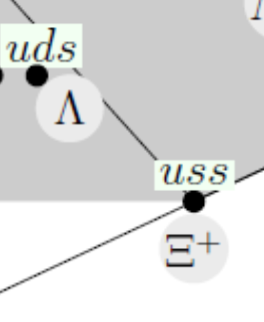
Baryon Supermultiplet symbol tweak
-
 Baryon supermultiplet

- Article(s)
- File:Baryon_Supermultiplet_using_four-quark_models_and_half_spin.png#Global file usage
- Request
- The image has two mistakes
- should be (towards the bottom, in the middle, next to uds)
- should be (towards the bottom right, next to uss).
- This will show the two symbols in need of updates.


The PNG description has the svg code for it. Headbomb {t · c · p · b} 01:50, 5 February 2025 (UTC)
- You can upload over the same image so that all the wikis get updated. Headbomb {t · c · p · b} 12:19, 7 February 2025 (UTC)
- Discussion
Space For Humanity logo
-
 Space for Humanity logo
- Article(s)
- Space For Humanity
- Request
Seems like a good SVG candidate to me. Indefatigable2 talk 22:14, 8 February 2025 (UTC)
Determinant parallelogram diagram
-
 Diagram A: ("Area parallelogram as determinant modified.svg")
The area of the parallelogram is the absolute value of the determinant of the matrix formed by the vectors representing the parallelogram's sides. -
 Diagram B: ("Area parallellogram as determinant.svg")
with (a,b) and (c,d) vertices labeled differently from Diagram A.


- Article(s)
- Determinant
- Request
- This image was kindly created by @TheWanderingTraders: in response to a request by me in January. Unfortunately, I did not realise that the label of the top vertex needs to be changed from "(a+c, b+d)" to "(a+b, c+d)" and I did not include that in my request. Someone at Talk:Determinant#Using_column_vectors_to_represent_points has now noticed that the image is not quite right.
- Please can someone now make this change.
- [By the way, you might wonder if a change is needed to "ad-bc", but that is the normal expression for the determinant of a 2x2 matrix and so it should not be changed.] -- JonH (talk) 20:55, 10 February 2025 (UTC)
- @JonH: Done QuickQuokka [talk • contribs] 07:19, 11 February 2025 (UTC)
- @JonH:
- Discussion
- @JonH: Given your choice of (a,b) and (c,d), the top vertex should remain (a+c,b+d)... the top vertex label is not the problem. Looking at the second diagram on this web page, for the (a,b) and (c,d) you have chosen, the correct formula for Diagram A area is bc-ad—which yields a positive number. I've added Diagram B above, which has the (a,b) and (c,d) labels switched versus yours. Would you rather just use Diagram B which has the determinant-familiar ad-bc, or add "absolute value symbols to the formula in Diagram A? I'm not sure what the goal is with this request. Please clarify. —RCraig09 (talk) 04:27, 16 February 2025 (UTC)
- To try to clarify this, I will set out some of the history:
- In 2007, File:Area parallellogram as determinant.svg was created with vertices (0, 0), (c, d), (a + c, b + d) and (a, b) reading anticlockwise.
- In 2009, it was changed to have vertices (0, 0), (a, b), (a + c, b + d) and (c, d).
- Years passed with no changes.
- In 2024, I started a discussion where I pointed out that the article Determinant used the row vectors of the matrix to represnt points, and that nowadays points are usually represented by column vectors, so the article could be simplified. The discussion confirmed this, but no change was made immediately.
- In January 2025, I made a request (now archived) to have a modified image with changes to two of the labels: from "(a, b)" to "(a, c)" and from "(c, d)" to "(b, d)".
- File:Area parallelogram as determinant modified was created with those two changes.
- The article Determinant was changed to be simpler and to use the modified image.
- On 7 February, it was pointed out at Talk:Determinant#Using_column_vectors_to_represent_points that the vertex (a + c, b + d) should now say (a + b, c + d). I had known back in 2024 that this change was needed, but I forget to include it in my first request. Sorry.
- On 10 February, I created this request to change the third vertex.
- On 11 February, @QuickQuokka: made the requested change, so the vertices were in the order (0, 0), (a, b), (a + b, c + d) and (b, d) reading anticlockwise.
- At 20:25 12 February, 2025 (UTC), I was happy with the changed image, so I noted on the Determinant talk page that it was now fixed, and clicked a link to thank QuickQuokka.
- An hour later, the image was changed to have the vertices in the order (0, 0), (c, d), (a + c, b + d) and (a, b).
- As @RCraig09: says, the diagram is now wrong because bc-ad is negative. But it is also wrong because it is using the row vectors to represent points and so it does not correspond to the text of the Determinant article.
- The simplest fix is to revert File:Area parallelogram as determinant modified to the version dated 07:19, 11 February 2025. I can do that, but there has also been a change to the transparent background which might be desirable, so I will wait to allow further discussion.

- By the way, the Stack Exchange page linked to above includes a diagram dated 1985, and seems to be using the older convention of row vectors to represent points. JonH (talk) 19:05, 23 February 2025 (UTC)
- I have an engineering background and understand the math basics, but here on Wikimedia I'm a Graphics Dude who's waiting for a concise request or instruction on what exactly is needed. It sounds like JonH is calling for more discussion, so I'll not take any action until the goal is clearly expressed. —RCraig09 (talk) 22:52, 23 February 2025 (UTC)
Create a vector version
-
 Logo for Long Wall (aerospace company)
- Article(s)
- Long Wall (aerospace company)
- Request
- Was wondering whether someone wants to create a vector version of this file. It was originally uploaded as non-free content, but it's too simple to be eligible for copyright protection under US copyright law per c:COM:TOO US. The webp file doesn't look too bad, but this might work better as a vector version since the white background can then probably be removed. The file is eventually going to be moved to Commons; so, the vector version could be uploaded there as well. -- Marchjuly (talk) 13:11, 21 February 2025 (UTC)
- Discussion
UEFA Super Cup logo
PDF File. أحمد 04 (talk) 13:52, 25 February 2025 (UTC)
Proposed flags of three U.S. states from 1976


/https%3A%2F%2Fstorage.canalblog.com%2F02%2F82%2F395634%2F20121802_o.jpg)
- Article(s)
- Flag of Alaska, Flag of Connecticut, Flag of Oregon, Proposed flags of U.S. states
- Request
- Could anyone please create SVG files for the following three U.S. state flag proposals from 1976:
- 1) Joan Altabe's proposed flag for Alaska, as seen here (at the top).
- 2) Atle Grahl-Madsen's proposed flag for Connecticut, as seen here (at the top).
- 3) Jean-Claude Muller's proposed flag for Oregon, as seen here (at the bottom).
- Thanks. Snow Lion Fenian (talk) 02:41, 26 February 2025 (UTC)
- @Snow Lion Fenian I made the flags because they were simple, but I'm not sure if this competition is important enough to be mentioned in so many articles. Swiãtopôłk (talk) 20:16, 26 February 2025 (UTC)
- Discussion